Optical Time-of-Flight (ToF) sensing and lock-in detection

Distance measurements is important for a lot of applications, such as 3D imaging and depth sensing. One common method for distance measurement is by using optical time-of-flight. I will introduce two concepts: (a) The time-of-flight Principle and (b) lock-in detection/amplification to explain how it works.
The simplest model of Time-of-Flight (ToF)
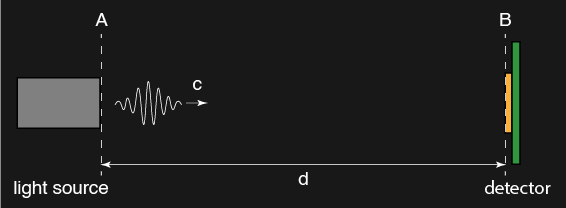
In a nutshell, optical time-of-flight (ToF) is a technique to measure distance from A to B.
A simple equation that relates speed \(c\), distance \(d\), and time \(t_{AB}\) is as follows.
\[c = \frac{d}{t_{AB}}\]where:
- \(c\) is the speed of light (\(\approx 3\times10^8\) m/s),a constant.
- \(d\) is the distance from A to B.
- \(t_{AB}\) is the time needed for light to travel from A to B.
Since \(c\) is a constant, if we know \(t_{AB}\), then we can calculate \(d\).
The simplest model is not practical
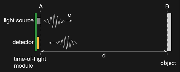
However, the above method will need a light source at point A and a detector at point B, and they need to be connected such that the detector knows when a light pulse get emitted from point A, mark at time 0, and when the pulse arrive at point B, mark as t. This makes no sense. Do I have to use a cable to connect the light source and detector? Do I need to place a sensor to every point I want the distance measured? How can I make tens, or hundreds, or thousands of measurements?
ToF device usually has the light source and detector packaged together. If we want distance from A to B, put the device at point A, then measure the time needed for light to get reflected from point B back to point A.
where:
- \(c\) is the speed of light (\(\approx 3\times10^8\) m/s),a constant.
- \(d\) is still the distance from A to B, \(2\cdot d\) is distance from A to B, then back to A.
- \(t_{ABA}\) is the time needed for light to travel from A to B, then back to A.
Now we ask…how can we measure the time needed for light to travel?
How to measure optical ToF?
Let’s say point B is at 10 m, the time needed for light to travel round trip is ~67 ns! If we send an optical pulse out from A, it will come back at ~67 ns! We are probably going to measure distance <10 m too, how are we suppose to detect that ns of time difference?
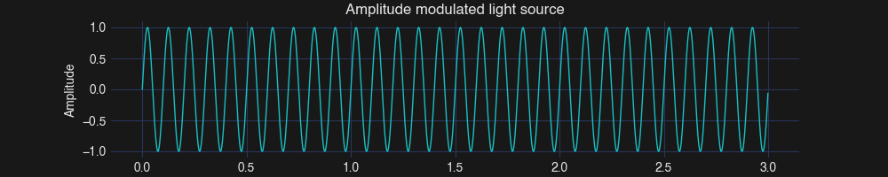
A way to detect this small change is by lock-in detection or amplification, also called indirect ToF (iToF) measurement. We will use a light source that is amplitude modulated, i.e.
\[S(t) = A_1\cdot sin(2\pi ft)\]where:
- \(S(t)\) is the amplitude modulated light source.
- \(f\) is the modulation frequency (a design choice).
- \(A_1\) is the amplitude.
- \(t\) is time, a independent variable.
When this light \(S(t)\), emitted from point A, get reflected from point B and then get detected at A, it becomes:
\[D(t) = A_2\cdot sin(2\pi ft + \phi_{ABA})\]where:
- \(D(t)\) is the detected light.
- \(A_2\) is the amplitude, usually much smaller than \(A_1\), depending on the reflectivity of point B.
- \(f\) is the modulation frequency, does not change.
- \(\phi_{ABA}\) is the phase shift of the detected light, from A to B, then back to A.
Here, if we can measure \(\phi_{ABA}\), then can know the time needed for light to travel from A to B, then back to A, since,
\[\phi_{ABA} = 2\pi ft_{ABA}\]Lock-in detection
Lock-in detection can help us to get \(\phi_{ABA}\). It will multiply \(D(t)\) to two reference signals, i.e.
\[R_1(t) = sin(2\pi ft)\]\[R_2(t) = cos(2\pi ft)\]For the multiplication of \(R_1(t)\), it gives an in-phase component \(I\).
\[I = D(t)\cdot R_1(t) = A_2sin(2\pi ft + \phi_{ABA})\cdot sin(2\pi ft)\]Using trigonometric identity, we can get,
\[I = \frac{A_2}{2}cos(\phi_{ABA}) - \frac{A_2}{2}cos(4\pi ft + \phi_{ABA})\]A simple low pass filter to extract the DC term can give us:
\[I = \frac{A_2}{2}cos(\phi_{ABA})\]Following the same treatment, the multiplication of \(R_2(t)\) gives an quadrature component \(Q\). After a low-pass filter to extract the DC term,
\[Q = \frac{A_2}{2}sin(\phi_{ABA})\]We can now solve,
\[\phi_{ABA} = arctan\left(\frac{Q}{I}\right)\]Hence, we can get \(t_{ABA}\).
Lock-in detection in action
Let’s see how lock-in detection works in action. First, I define a light source with an amplitude of 1 and a modulation frequency of 10 MHz.
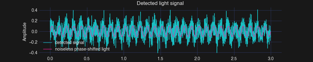
Assume the distance I want to measure is exactly 1m and the reflectivity of the object is 10%. The light that travel back will have a phase-shift and an amplitude of 0.1 (Denoted in “noiseless phase-shifted light”). To be more realistic, I also add some normal-distributed noise with standard deviation of 0.1 to the detected signal (Denoted in “detected signal”).
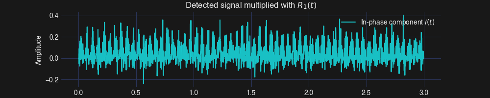
Then, we can multiply the detected signal with \(R_1(t)\) to get the in-phase component \(I\) and \(R_2(t)\) to get the quadrature component \(Q\). Below shows the in-phase component \(I\).
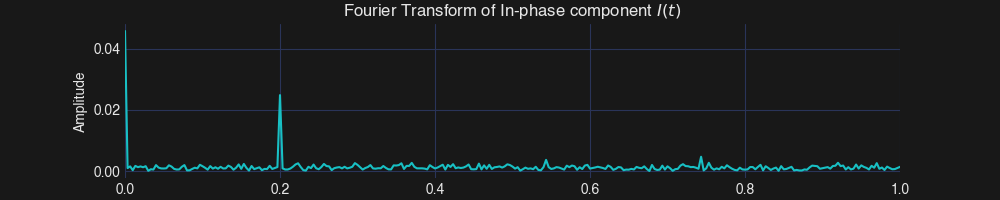
After that, we can extract the DC term of \(I\) and \(Q\) to complete the calculation. Below shows the Fourier transform of \(I\). The DC term of \(I\) is ~0.0458 and \(Q\) is ~0.0189.
We measured a distance of 0.93 m (Ground-truth is 1m). It is remarkable! The error is <7% with this noisy detected signal! In fact, the SNR of the detected signal is ~0.7 only!
This demonstrate the power of lock-in detection. This is why it is also called lock-in amplification, since it is able to “amplify” a noisy signal.
Script for simulation:
See below or use this link for the script with plotting.
import numpy as np
import matplotlib.pyplot as plt
from scipy.fftpack import fft

# Parameters
fs = 10e8       # Sampling frequency (Hz)
duration = 3e-6  # Signal duration (seconds)

source_modulation = 10e6  # Frequency of the modulation (Hz)
source_amplitude = 1    # Amplitude of the desired signal

noise_std = 0.1   # Amplitude of the noise
reflectivity = 0.1      # Reflectivity of the object is 10%

distance = 1                # Distance between the light source and the object (m)
c = 3e8                     # Speed of light (m/s)
time_ABA = 2*distance/c
phase_signal = 2*np.pi*source_modulation*(time_ABA)    # Phase of the detected signal (radians)

# Time vector
t = np.linspace(0, duration, int(fs * duration), endpoint=False)

# Generate the light source
signal = source_amplitude * np.sin(2 * np.pi * source_modulation * t)

# Generate the detected signal
np.random.seed(1)
noise = noise_std * np.random.normal(size=t.shape)
detected_signal = reflectivity * source_amplitude * np.sin(2 * np.pi * source_modulation * t + phase_signal) + noise

# Reference signals (sin and cos for lock-in detection)
f_reference = source_modulation
ref_sin = np.sin(2 * np.pi * f_reference * t)
ref_cos = np.cos(2 * np.pi * f_reference * t)

# Perform lock-in detection
I = detected_signal * ref_sin   # In-phase component
Q = detected_signal * ref_cos   # Quadrature component

# Fourier Transform of the noisy signal
freqs = np.fft.fftfreq(len(detected_signal), 1 / fs)
fft_detected_signal_mixed_sin = np.abs(fft(I)) / len(I)
fft_detected_signal_mixed_cos = np.abs(fft(Q)) / len(Q)

# DC component of the mixed signals
DC_I = np.mean(I)
DC_Q = np.mean(Q)

# Calculate amplitude and phase
amplitude_detected = 2 * np.sqrt(DC_I**2 + DC_Q**2)
phase_detected = np.arctan2(DC_Q, DC_I)

time_detected = phase_detected/(2*np.pi*source_modulation)
distance_detected = time_detected*c/2

# Display results
print(f"Detected Amplitude: {amplitude_detected:.3f}")
print(f"Detected Phase: {phase_detected:.3f} rad")
print(f"Detected distance: {distance_detected:.3f}")